


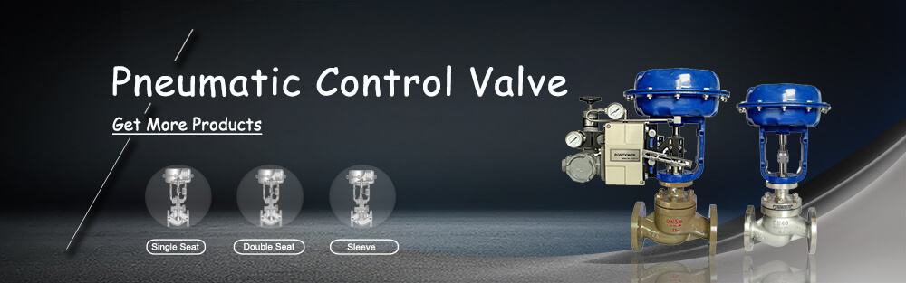
What Is Pneumatic Control Valve?
Pneumatic Control Valve is to compressed air as the power source, to the cylinder as the actuator, and with the help of positioner, converter, solenoid valves and other accessories to drive the valve, to achieve on-off or proportional regulation, receive the control signal of the industrial automation control system to adjust the flow, pressure, temperature and other process parameters. Pneumatic Control Valve is characterized by simple control, rapid response, and essentially safe, no additional explosion-proof measures. However, the operation of the valve occasionally fails, following we will explain in detail the regulator valve may appear 5 kinds of failure and its treatment.
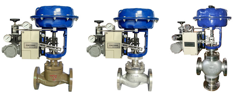
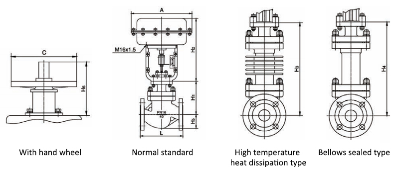
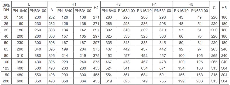
Type Single-seat, double seat, sleeve type Size Range(Inch) DN20 to DN200 (3/4″ to 8″) Pressure 16 / 40 / 64 bar (232 / 580 / 928 psi) TemperatureStandard type: -20℃ to 200℃ (-4°F to 392°F)Low-temperature type:-60℃ to 196℃ (-76°F to 384.8°F)Cooling type:-40℃ to 450℃ (-40°F to 842°F)Connection Options Flanged or Welded Valve Material WCB, CF8, CF8M, Cast iron Seal Material PTFE Pneumatic Accessories Positioner, F.R.L, pneumatic solenoid valve and limit switch Flow characteristics Equal percentage, linear, quick-opening Actuator Type Multi-spring diaphragm actuator Actuator Action type Direct action, reverse action Spring range 20 to100KPa, 40 to 200KPa, 80 to 240KPa Supply pressure 0.4~0.5MPa Adjustable range 50:1 Price Click here to get a better price!
5 Common Faults Of Pneumatic Control Valve:
1. The Control Valve doesn’t work
First confirm whether the gas source pressure is normal, find the gas source failure. If the air pressure is normal, determine whether the amplifier of the positioner or the compressed air converter has an output.
2. Valve Blockage
In such cases, you can quickly open, close the secondary Line or control valve, so that stolen goods from the secondary line or control valve was medium run. In addition, you can also clamp the stem with pipe tongs, in addition to the signal pressure, positive and negative force rotating stem, so that the valve core flash card place.
If can not solve the problem, can increase the gas source pressure, increase the drive power to move up and down repeatedly several times, can solve the problem. If still can not move, then need to do to control valve disassembly processing, of course, this work requires strong professional skills, must be done with the assistance of professional and technical personnel, otherwise more serious consequences.
3. Valve leak
The leakage of the pneumatic control valve is usually caused by internal leakage of the control valve, leakage of packing and leakage of valve core and valve seat.
3.1 Internal Leakage
Valve stem length discomfort, gas valve stem too long, stem up (or down) distance is not enough, resulting in a gap between the SPOOL and valve seat, can not fully contact,
3.2 Packing Leakage
In order to make stuffing easy to load, chamfer at the top of the stuffing box, put the metal protecting ring with small erosion-resisting gap at the bottom of stuffing box, notice that the contact surface between the protecting ring and stuffing can not be inclined plane.
In order to prevent stuffing from being pushed out by medium pressure. The surface of the stuffing box and the stuffing contact part should be finished to improve the surface finish and reduce the stuffing wear. Flexible graphite is chosen as the filler because of its good air tightness, small friction force, small change in long-term use, small wear and tear, easy to maintain, and the pressure resistance and heat resistance are good because the friction force does not change after the gland bolt is tightened again free from corrosion of internal media, and the stem and stuffing box internal contact of the metal does not pitting or corrosion.
In this way, effectively protect the valve stem packing letter seal, ensure the reliability of packing seal, service life is also greatly improved.
3.3 Valve Core, Valve Seat Deformation Leakage
Selection of corrosion-resistant materials, the existence of pitting, trachoma and other defects of the product to be resolutely eliminated. If the deformation of the valve core and seat is not too serious, fine sandpaper can be used to grind, eliminate traces, improve sealing finish, to improve sealing performance. If the damage is serious, you should replace the new valve.
4. Oscillates
The spring stiffness of the control valve is insufficient, the output signal of the control valve is unstable and changes rapidly, which easily causes the control Valve oscillation.
As the causes of oscillation are various, it is necessary to make a concrete analysis of specific problems. For example, the adjusting valve with a large rigidity spring is chosen, and the piston execution structure is used instead.
The pipe and the base are violently vibrating, and the vibration interference can be eliminated by increasing the support.Change the different structure of the control valve. Working in a small opening caused by the oscillation, is caused by improper selection, specifically, because the valve flow capacity C value is too large, must be re-selection, choose the flow capacity of C value is small or the use of sub-range control or the use of parent valve to overcome the control valve operating in a small opening caused by the oscillation.
5. Noise
5.1 The Method Of Eliminating Resonance Noise
Only when the control valve resonance, there is energy superposition and produce more than 100 decibels of strong noise. Some show strong vibration, noise is not big, some vibration is weak, but noise is very big; some vibration and noise are bigger. This noise produces a monotonic sound at a frequency of between 3000 and 7000 Hz. Obviously, by eliminating the resonance, the noise will naturally disappear.
5.2 Cavitation Noise Abatement
Cavitation is the main source of hydrodynamic noise. When cavitation occurs, the bubble will burst and produce high-speed impact, resulting in strong local turbulence and cavitation noise. The noise has a wide frequency range and produces a lattice sound similar to that produced by a fluid containing gravel. Eliminating and reducing cavitation is an effective way to eliminate and reduce noise.
5.3 Use The Thick Wall Method
Using the thick-walled tube is one of the methods to deal with the sound circuits. Using a thin wall can increase the noise by 5 DB, using a thick wall tube can reduce the noise by 0 ~ 20 DB. The thicker the wall of the same diameter, the larger the diameter of the same wall thickness, the better the noise reduction effect. For DN200 pipes with wall thickness of 6.25,6.75,8,10,12.5,15,18,20 and 21.5 mm, the noise can be reduced by-3.5,-2(i.e. increased) , 0,3,6,8,11,13 and 14.5 DB respectively. Of course, the thicker the wall, the higher the cost.
5.4 Use Sound Absorbing Material Method
This is also a more common, the most effective way of sound path processing. Sound-absorbing material may be used to encase the noise source and the pipe behind the valve. It is important to point out that the effectiveness of noise abatement ceases wherever sound-absorbing material is packaged and thick-walled tubes are used, since noise can travel long distances through fluid flow. This approach is applicable where the noise level is not very high and the pipe length is not very long, as it is a more costly approach.
5.5 Series Silencer Method
It is suitable for the silencing of aerodynamic noise. It can effectively eliminate the noise inside the fluid and suppress the noise level transmitted to the solid boundary layer. This method is most effective and economical where the mass flow rate is high or the ratio of pressure drop before and after the valve is high. The use of absorption type series silencers can greatly reduce noise. Economic considerations, however, are generally limited to a attenuation of about 25 DB.
5.6 Enclosure Method
Use enclosures, houses and buildings to isolate the source of the noise from the outside environment to within acceptable limits.
5.7 Series Throttling
When the pressure ratio of the control valve is high (△ P / p 1≥0.8) , the method of series throttling is used to disperse the total pressure drop on the control valve and the fixed throttling element behind the valve. DIFFUSERS, porous restrictors, for example, are the most effective means of reducing noise. In order to get the best diffuser efficiency, the diffuser (solid shape and size) must be designed according to the installation of each piece, so that the noise level generated by the valve is the same as that generated by the diffuser.
5.8 Use A Low Noise Valve
Low noise valve according to the fluid through the spool, seat of the tortuous flow path (multi-channel, multi-channel) gradually slow down to avoid any point in the flow path to produce supersonic. There are a variety of forms, a variety of low-noise valve structure (there is a special system design) for use when choosing. When the noise is not very big, choose low noise sleeve valve, can reduce noise 10 ~ 20 DB, this is the most economical low noise valve.
Post time: Nov-25-2021